
In This Article
QUICK ANSWER · PRODUCTION LAYOUT
Is a Linear or U-Shaped Food Production Layout Better?
Choose the arrangement that supports the actual process sequence, material and people flows, hygienic boundaries, access and expansion plan within the candidate building. A straight-through layout can align well with receiving and shipping at opposite ends. A U-shaped arrangement can bring some activities closer together, but may also concentrate traffic or complicate separation. Neither shape is inherently more efficient or more hygienic.
Compare both concepts using the same products, saleable output, operating schedule and equipment boundaries. Test the flows and interfaces before turning a preferred shape into a fixed design instruction.
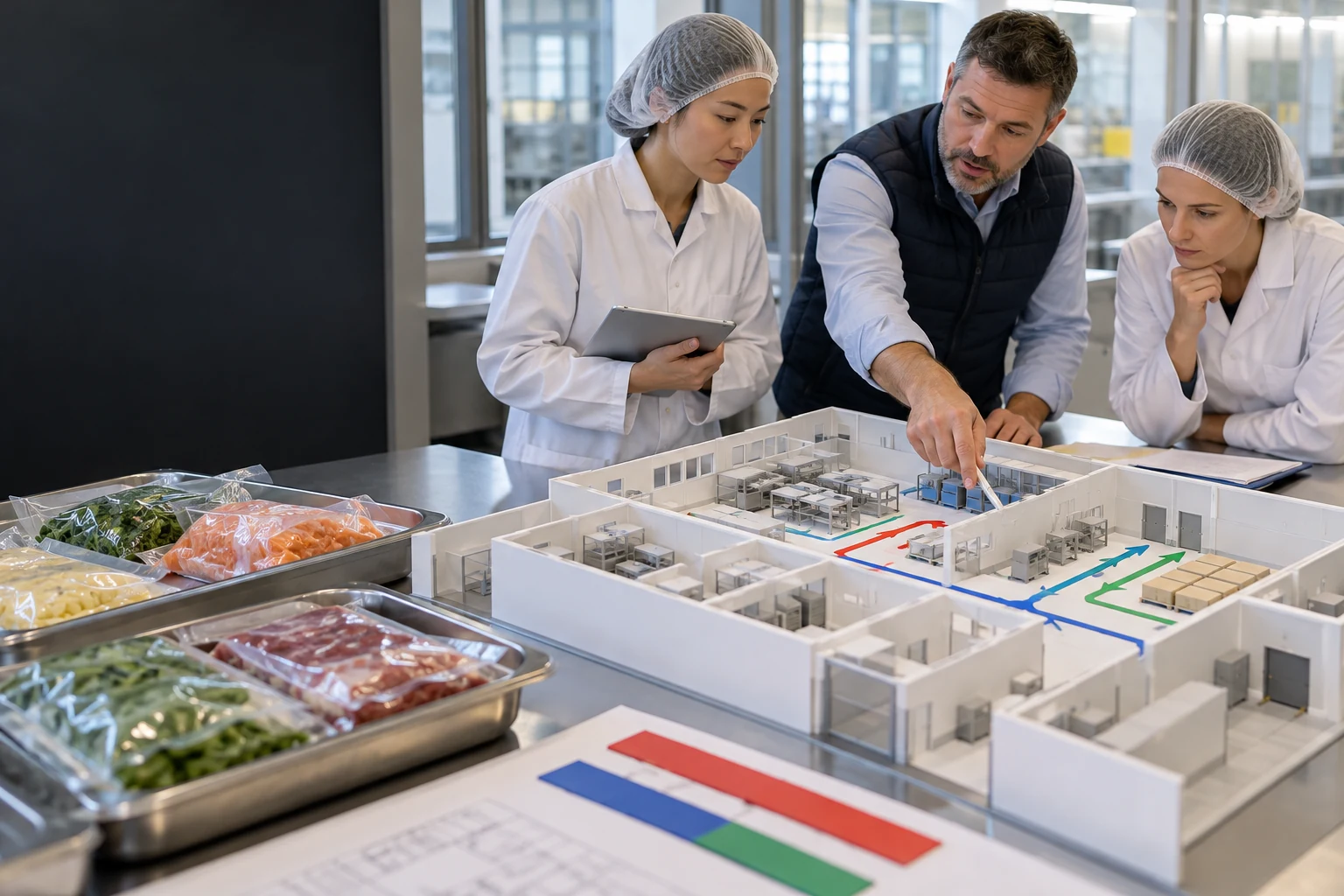
A neat line on a floor plan can conceal a difficult factory. Ingredients may cross finished goods, packaging materials may arrive through the wrong work area, and a short walking route may pass directly through a boundary that the operation needs to protect.
A useful food production line layout comparison asks how the plant will work, not which geometric shape looks simpler. This guide explains how owners can compare linear and U-shaped concepts without confusing a compact footprint with a complete operating solution.
1. Start with the Required Flow, Then Test the Geometry
Write the process sequence before drawing a line shape. Identify receiving, ingredient staging, preparation, processing, product holding, packaging, finished-goods staging and dispatch as applicable to the business. Include waste, returns and cleaning activities rather than treating them as items to fit around the production line later.
A linear concept often describes a progression across the building. A U-shaped concept brings the beginning and end of a sequence nearer one another. Those descriptions do not establish the detailed handling routes, separation or staffing requirements. The relevant unit operations and interfaces still have to fit.
Gray’s food plant design guidance emphasizes considering production and food safety during facility planning. For a layout comparison, that means evaluating the operation while alternatives are still flexible. A preferred shape should emerge from that evaluation rather than substitute for it.
Keep the first drawings conceptual. The purpose is to expose tradeoffs and decide which arrangement deserves development. Dimensions, equipment clearances and specialist requirements become progressively firmer as the selected concept is engineered.
2. Compare the Same Production Business in Both Layouts
Use one approved product list, pack mix, capacity basis and shift schedule. If the linear option is designed for long campaigns while the U-shaped option is designed for many short runs, the comparison combines a geometry decision with a different operating model.
List the expected material movements for a representative production period. Include ingredient delivery quantities, packaging replenishment, finished pallet movements and waste collection. Identify movements driven by a batch or changeover rather than simply by the number of saleable units.
State the equipment and utility boundaries used in each concept. A drawing that omits the same holding or cleaning functions in one alternative will appear smaller without actually providing the same capability. Ask the team to reconcile the scope before discussing area savings.
DPS’s conceptual process and facility planning can help establish this common basis. A useful engagement compares defined operating arrangements and identifies the important interfaces, rather than choosing a line shape in isolation from the product and production requirements.
3. Test Columns, Docks and Clearances Before Refining the Line
The building can strongly influence the viable arrangement. Review column locations, clear height, available production area, dock positions, floor conditions and access routes. Distinguish measured information from assumptions taken from incomplete landlord or sales drawings.
A long narrow shell may favor a different sequence from a broad building with receiving and shipping on the same side. A U-shaped concept can appear attractive until the internal turning and staging requirements are drawn. A straight-through concept can appear simple until its long replenishment routes are counted.
Locate the major support functions at the same time. Ingredient rooms, quality activities, personnel access, utilities and cleaning provisions influence the productive area and its boundaries. Leaving these functions outside the first test fit can create a misleading impression of spare space.
If the building is not yet selected, use the comparison to create site criteria. The owner can then search for a shell that supports the intended operation, instead of forcing a fixed production diagram into whatever property happens to be available.
4. Linear vs U-Shaped Layouts: A Decision Comparison
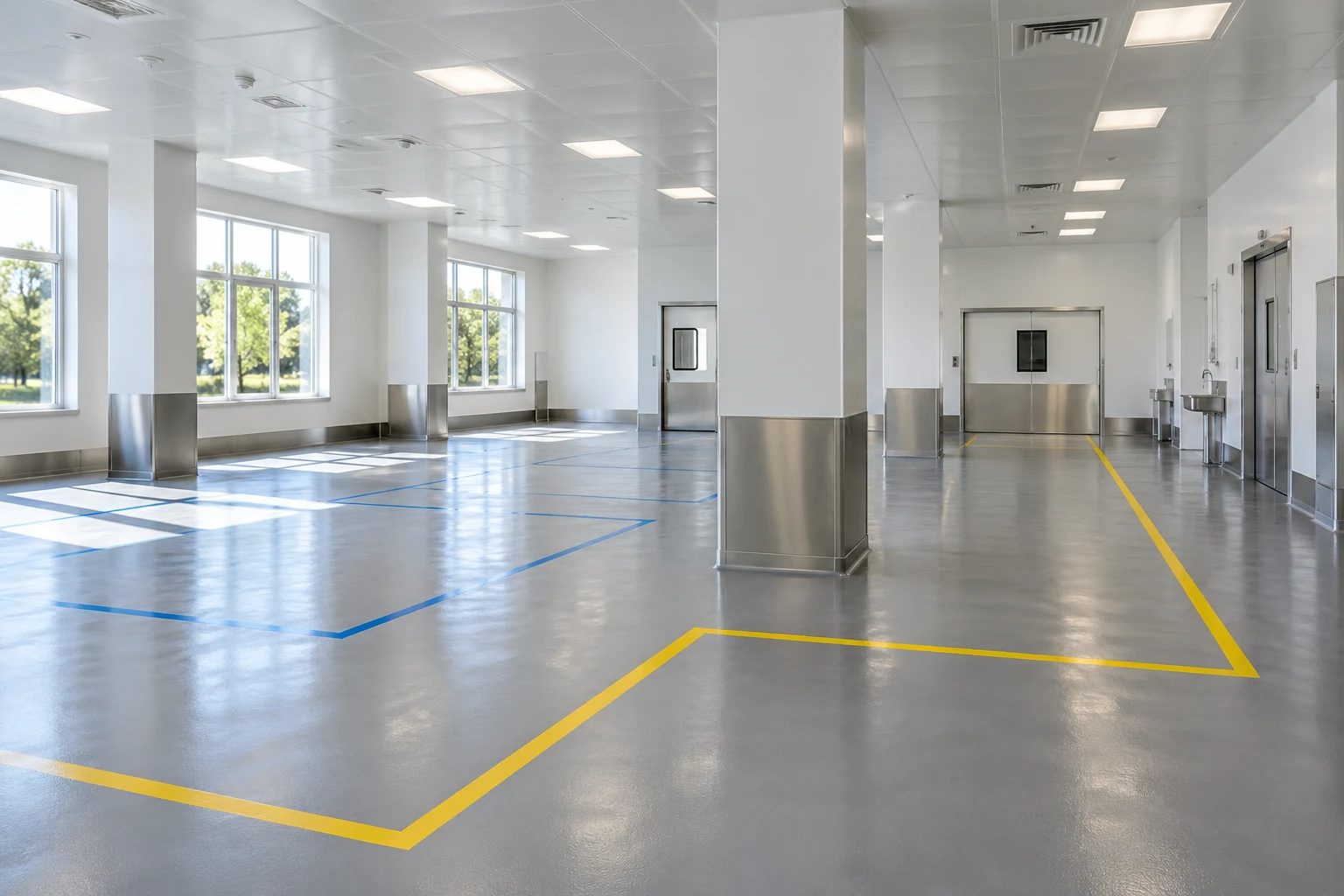
The following comparison identifies questions, not universal winners. The actual result depends on the product sequence, building and operating model. Use it during concept development and replace general observations with project-specific evidence as the alternatives become clearer.
| Decision Factor | Linear Concept | U-Shaped Concept | Verify |
|---|---|---|---|
| Overall progression | Can support movement across the building | Brings start and end closer | Actual material routes and separation |
| Dock relationship | May suit opposite receiving and shipping ends | May suit shared-side logistics | Vehicle, staging and people interfaces |
| Operator movement | Can create longer travel between ends | May shorten selected routes | Tasks, staffing and safe access |
| Growth | May extend along an axis | May require a different expansion direction | Future work and operating disruption |
Ask which observation is important to the business and which remains speculative. A shorter route deserves credit only when it is a route the operation will actually use. A theoretical expansion direction deserves credit only when the site and utility plan can support it.
5. Separate Raw, Work-in-Process and Finished-Product Movements
Map the states in which materials move, rather than using one undifferentiated arrow for “product.” Raw ingredients, exposed product, sealed packs and finished pallets may have different handling and separation needs. The quality and process teams should define the relevant boundaries.
A U-shaped concept can bring raw receiving and finished dispatch physically closer. That may improve a logistics arrangement, but it also makes the interface worth examining carefully. A linear concept can support a clear progression, yet still create crossings if replenishment or waste routes are not developed.
Identify the transfer points and the activities performed there. Does a container wait, get sampled, change handling method or cross a controlled boundary? Those details affect staging, staffing and space. A simple arrow cannot represent the entire operating requirement.
Review reverse flows as well: returns, rejected materials, empty containers and rework where appropriate. They should have defined management routes. A concept that works only when every movement follows the main forward arrow has not yet been tested against the full operation.
6. Design People Movement Around Actual Work
List the activities performed by operators, material handlers, quality personnel, supervisors and visitors. Show where they enter, what tasks they perform and which areas they need to access. A short distance between two workstations does not help if the person must take a controlled route around a boundary.
Compare staffing assumptions consistently. A concept may appear to need fewer people because it omits replenishment, sampling or changeover tasks. Map those activities before claiming a labor benefit. The owner should understand which responsibilities can genuinely be combined and which require separate attention.
OSHA’s warehousing guidance highlights material-handling and storage hazards. In a production-layout study, the practical response is to examine movement interfaces with the appropriate safety specialists. This article does not prescribe aisle dimensions or substitute for a site-specific safety review.
Check where people wait and where work accumulates during interruptions. A normal-running arrangement can behave differently during a product hold, packaging stop or shift transition. Those scenarios often reveal congestion that a clean concept drawing does not show.
7. Include Packaging Replenishment and Buffers
Packaging materials need a route from storage to the point of use. Empty containers, closures, labels and secondary packs can consume staging space and handling effort even when the main process line is compact. Include the actual replenishment method in both alternatives.
Define the role of buffers. They may accommodate differences between process and packaging rates or allow selected activities to continue during a short interruption. Their required capacity and operating limits should be established by the design team, not assumed from an available empty space.
Consider the intended product and format mix. A plant running one long format campaign can have different staging needs from a facility changing packs frequently. Identify where materials for the next campaign will wait and how incorrect materials are controlled.
8. Connect the Line Layout to Receiving and Shipping
Receiving and shipping are parts of the factory system, not merely the ends of a process arrow. Include vehicle patterns, delivery sizes, outgoing shipment profiles and the staging required before materials move into or out of the building.
A shared dock side may support a U-shaped overall arrangement, but test whether incoming and outgoing activity overlap. A straight-through arrangement with docks at opposite ends may simplify some movements while increasing other site or building requirements. The correct comparison includes both inside and outside flows.
Include rejected deliveries, quality holds and returned materials in the review. Those events need a defined place and route so they do not consume working staging areas unexpectedly. The owner should explain the commercial practices that drive their frequency.
Use the same storage and dispatch assumptions for both alternatives. If one concept relies on frequent deliveries and the other on larger inventories, show that as a separate operating choice. Otherwise, a layout preference may be receiving credit for a different supply-chain policy.
9. Quantify Representative Movements Before Claiming Efficiency
An original teaching example compares sixty loaded movements in a representative period. It includes twenty ingredient transfers, thirty finished-product transfers and ten waste movements. Route lengths are invented conceptual distances, not measured plant results or recommended design values.
Multiply each movement count by its route length. The linear option totals 2,950 meters of loaded travel; the U-shaped option totals 2,450. The U-shaped concept reduces the total in this example but lengthens the finished-product route. That is a tradeoff to investigate, not a universal verdict.
| Movement | Count | Linear Route / Total m | U-Shaped Route / Total m |
|---|---|---|---|
| Ingredients | 20 | 60 / 1,200 | 35 / 700 |
| Finished product | 30 | 45 / 1,350 | 50 / 1,500 |
| Waste | 10 | 40 / 400 | 25 / 250 |
| Total | 60 | 2,950 | 2,450 |
Do not translate the difference directly into a staffing or financial saving. Travel speed, handling, traffic, empty returns and work allocation have not been modeled. Use the result to identify the routes and assumptions that deserve a more detailed study.
10. Visualize the Distance Comparison with Its Limitations Visible
The difference in the teaching example is 500 meters, approximately seventeen percent of the linear concept’s loaded travel. The chart presents the totals on the same scale. It does not measure production efficiency, labor productivity, safety or food quality.
Illustrative loaded travel · meters per defined period
Linear concept · 2,950
U-shaped concept · 2,450
Bars use 2,950 meters as the scale. Original example; no measured DPS performance claim.
For a real study, use route definitions that can be checked on the drawings and movement counts supported by the production schedule. Test a busy period and a changed product mix. The preferred arrangement should remain understandable when the owner asks which assumptions produced the result.
If two concepts have similar travel totals, examine the distribution. A small overall difference can conceal a difficult crossing or a long route for a frequent manual task. Totals help summarize a study; the routes explain it.
11. Let the Food Safety Plan Define the Relevant Boundaries
Neither linear nor U-shaped geometry creates hygienic separation automatically. The product and process determine where separation, access control or other provisions may be required. The responsible quality and engineering specialists should define those requirements and evaluate how each concept implements them.
21 CFR 117.20 addresses plant and grounds for applicable operations, including space and arrangements relevant to sanitary production. Use the applicable requirements as inputs to the layout. Do not treat a generic diagram in a planning article as evidence of compliance.
Consider personnel, materials, air, cleaning and waste together where they affect the defined boundaries. A concept may have an orderly product route while people or materials cross it in a way that the operating plan cannot support. Those interfaces deserve explicit review.
Include changes between product campaigns. The intended cleaning and release sequence may affect whether areas can be shared or used simultaneously. A layout comparison should reflect the actual product program and approved quality approach, rather than a simplified drawing of one favorable recipe.
12. Preserve Installation, Cleaning and Service Access
Equipment footprints alone do not describe the space needed to operate a line. Include access for operators, cleaning activities, inspection, parts removal and eventual equipment replacement. Supplier information and the relevant specialist reviews should establish the actual requirements.
A compact U-shaped arrangement may bring equipment closer but reduce useful access between legs of the line. A linear arrangement may provide clearer sides while extending the building footprint. Test both with realistic working zones rather than using the smallest physical outline in a brochure.
Show how major items enter the building. A future machine or replacement component may need a route that conflicts with an operating area. Identify removable construction provisions or other arrangements where they are part of the concept, and price them explicitly.
The owner should also ask how the line behaves when one activity is unavailable. Can people reach the affected area without crossing unsuitable routes? Can materials be staged without blocking another function? These questions connect layout compactness to the practical resilience of the operating plan.
13. Coordinate Utility and Cleaning Routes with the Geometry
Locate major utility interfaces, distribution routes and cleaning provisions during concept development. A line shape can affect distances, access and the location of shared systems. The process and facility teams need a common basis so these support functions are not added after the productive area has been committed.
Keep the comparison at the right level of definition. Early drawings can identify major corridors and likely interfaces without pretending that pipe sizes, cable routes or cleaning circuits are complete. Record the information needed from suppliers and the decisions that must be confirmed later.
DPS’s process engineering and utility planning can bring these interfaces into the same concept review as the material flows. Ask the team to identify where an apparent area saving creates extra distribution work or a more difficult installation boundary.
Separate known scope from future provisions. A corridor reserved for expansion is a spatial choice; installing full future utility capacity is a different capital choice. Both may be relevant, but they should be explained and priced separately so the owner can compare their value.
14. Test the Second Line Before Choosing the First-Line Shape
Draw the likely expansion case while the initial layout remains flexible. Identify the future production sequence, material routes, utility connections and access for construction. A concept that fits the first line elegantly may leave an awkward or disruptive path to the second.
A linear arrangement may be extended along an available axis, or it may reach a site boundary. A U-shaped arrangement may preserve an adjacent bay, or it may occupy the space needed for later circulation. These outcomes depend on the actual building and parcel.
Define the expansion trigger and the business assumptions behind it. Do not purchase an oversized initial plant merely because a concept drawing shows a large future rectangle. Ask which low-cost spatial provisions preserve options and which commitments belong in a later investment decision.
Include the operating consequence of expansion. If the future work requires shutting down the initial line or moving material routes, show that in the comparison. The owner can then evaluate the full development strategy rather than rewarding a layout only for its opening-day appearance.
15. Use Decision Criteria That Cannot Hide a Critical Constraint
A weighted matrix can organize a comparison, but it should not allow a serious process or access problem to disappear inside a favorable total. Establish hard requirements separately, then compare the alternatives that can satisfy them.
| Type | Example Question | Evidence |
|---|---|---|
| Required operating fit | Can the concept support the agreed process and output? | Process sequence and capacity basis |
| Required boundaries | Can the quality and access requirements be implemented? | Relevant specialist reviews |
| Comparative performance | Which actual movements or tasks improve? | Route study and operating scenarios |
| Owner preference | Which arrangement better supports the growth strategy? | Phased site and capital plan |
Record why a score was assigned and what could change it. A number without an evidence note can make a subjective preference look like measured performance. The matrix should help leaders discuss the alternatives, not replace the engineering and operating reviews.
16. Run a Cross-Functional Test Fit Before Freezing the Layout
Review the same drawings with operations, quality, material handling, engineering and the owner’s capital team. Walk through receiving, a normal campaign, a changeover, a product hold and dispatch. Ask each participant to identify the routes and working areas used during those scenarios.
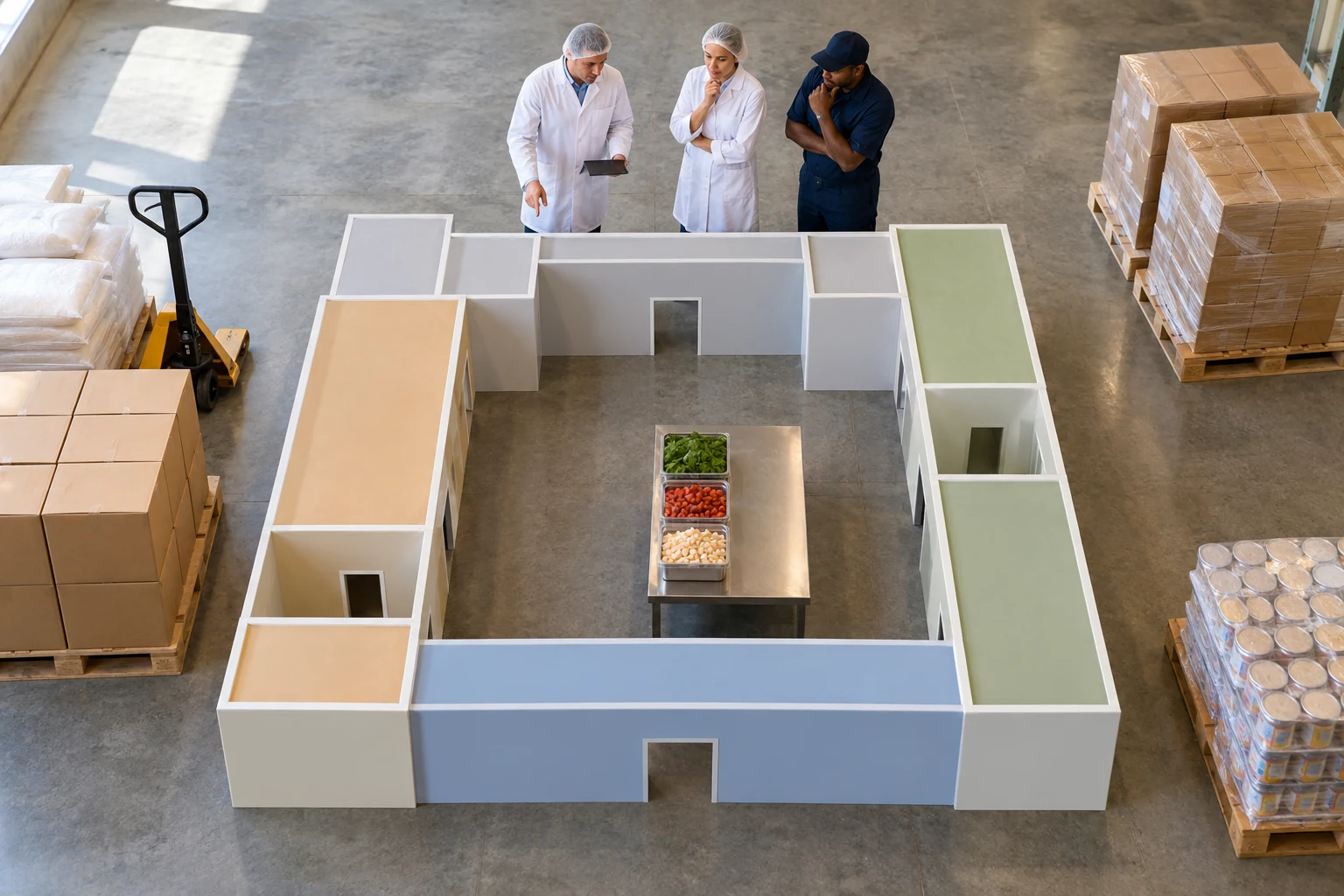
Use simple movable blocks or controlled drawing revisions to test alternatives quickly. At this stage, the benefit is the ability to expose a conflict before it becomes embedded in detailed design. Record what changed and which requirements the revision is intended to improve.
Conclude the review with open items, owners and decision dates. A workshop is useful when it produces a better defined basis for the next drawing issue, rather than simply a collection of comments that cannot be traced to a requirement.
17. Compare Installed Scope and Disruption, Not Only Floor Area
Area is one consequence of a layout. Installation work, utility routes, handling arrangements, access provisions and future construction can also affect investment and operation. Ask the estimate to follow the same boundaries for both concepts.
| Scope Item | Comparison Question | Avoid |
|---|---|---|
| Building fit-out | Are the same functions and boundaries included? | Comparing productive area with total plant area |
| Handling | What storage, staging and movement systems are required? | Crediting unmodeled labor savings |
| Utilities and cleaning | What distribution and access changes? | Omitting support scope from the compact option |
| Future work | How will expansion affect operating production? | Ignoring relocation and shutdown consequences |
Keep uncertainty visible when the concepts are preliminary. The decision may be to develop one option further, or to test a critical assumption before choosing. A concept estimate should support that next step without overstating the certainty of unfinished design work.
18. Turn the Shape Comparison into a Scoped Layout Decision
Bring DPS the product mix, production schedule, candidate building information and the practical problems the layout must resolve. Ask for alternatives evaluated against the same operating basis, with the major flows, utility interfaces and expansion assumptions visible.
The planning deliverable should explain why a concept is preferred and what remains to be verified. A useful conclusion might favor straight-through material movement while retaining a shared-side logistics arrangement, or reject both initial sketches in favor of another configuration. The objective is a workable factory, not loyalty to a diagram.
After choosing a concept, maintain the basis as equipment data and detailed engineering develop. If a major requirement changes, revisit the affected routes and interfaces. The comparison becomes valuable when its reasoning survives into the installed plant and remains understandable to the people who operate it.
19. Test Whether the Preference Survives a Different Product Mix
A layout selected for one representative day can be fragile when the commercial mix changes. Run a second scenario with more short campaigns, different pack formats or a different ratio of ingredients to finished pallets. Keep the changes explicit so the owner can see which business assumption changes the conclusion.
For example, a concept that shortens ingredient movement may look attractive when ingredient staging dominates activity. If the later business plan increases finished-pallet handling substantially, a longer dispatch route may become more important. The original travel total does not become wrong; it becomes evidence for a narrower operating case than management may have assumed.
Ask what practical provisions would make the preferred concept more adaptable. An additional staging location, a different door position or a reserved route may be worth evaluating, while a more extensive rearrangement may undermine the original concept. Price the relevant options rather than describing flexibility as a benefit that costs nothing.
20. Match the Routes to the Intended Handling Method
The same distance can have different operating consequences depending on what moves and how it moves. A manually handled container, a wheeled cart and a pallet movement do not require the same work areas or interactions. Define the intended handling method for each important route before using distance as a proxy for effort.
Include loading, unloading, turning, waiting and temporary staging in the review. A short route with repeated handling steps may be less attractive than a longer direct movement. Conversely, an apparently efficient transfer can create a difficult interface if its replenishment activity conflicts with people working nearby.
The material-handling and safety specialists should review the proposed methods and access arrangements. Use their requirements in both concepts and preserve the supporting assumptions. This keeps the geometric comparison connected to the real task, without turning a generic planning article into a prescriptive equipment or aisle design.
21. Food Production Line Layout FAQ
Is a U-shaped layout always more efficient?
No. It may shorten selected routes while lengthening others or concentrating traffic. Compare actual material movements, work tasks, access and boundaries under the same production schedule. A compact footprint does not establish a labor, energy or throughput benefit.
Does a linear layout automatically prevent cross-contamination?
No. Geometry alone does not establish hygienic separation. The product, process and quality plan determine the relevant boundaries. Review people, materials, cleaning and other interfaces with the responsible specialists, including the conditions during changes between campaigns.
Can two layouts be compared by square footage alone?
No. Confirm that both include the same process, support functions, staging, access and future provisions. Area can be one measure, but installed scope, operating routes and expansion consequences also affect the investment decision.
What information is needed for an early test fit?
Provide the product and packaging mix, saleable capacity, operating schedule, preliminary process sequence, building information and logistics assumptions. Mark unverified dimensions and supplier data. Include the decision the test fit must support and the constraints that cannot be traded away.
Does the travel-distance example predict staffing savings?
No. It counts invented loaded movements only and excludes empty returns, waiting, handling time and work allocation. It helps illustrate route tradeoffs. A staffing or financial conclusion requires a broader operating analysis with appropriate evidence.
Should the future second line affect the initial layout?
Yes, when expansion is part of a credible business strategy. Test future material routes, utility connections, access and construction effects. Separate spatial provisions that preserve an option from equipment or capacity that does not need to be purchased initially.
How should a preferred shape be documented?
Record the common production basis, alternatives, decision criteria, supporting evidence and unresolved items. Explain the tradeoffs rather than presenting the drawing alone. Maintain that record as detailed engineering and supplier information refine the concept.
How can DPS support this comparison?
DPS can connect conceptual process and facility planning with equipment, utility and phased-investment questions. Ask for a defined engagement comparing alternatives on the same basis. The exact deliverables and responsibilities should be agreed for the project.
Sources and Calculation Notes
Research checked October 27, 2026. Numerical illustrations and decision examples were prepared for this article; they are not supplier quotations, market benchmarks or DPS project results. Project-specific requirements and responsibilities belong in the agreed scope.
- Gray — Food plant design and construction. Early coordination of production, food safety and facility design.
- CRB — Food and beverage facilities. Integration of process, packaging, warehouse and facility systems.
- eCFR — 21 CFR 117.20. Plant space, construction and sanitary operation considerations.
- OSHA — Warehousing hazards and solutions. Safe storage, handling, racks and access.
- DPS — Capital Planning and Feasibility. Conceptual layouts, equipment and utility requirements, installed-cost planning and phased investment evaluation.