
In This Article
When Should a Food Plant Use Central CIP or Satellite Stations?
Compare the cleaning objects, physical routes, required concurrency and available utility conditions before choosing where CIP capability sits. Centralized CIP can consolidate equipment and media handling; satellite arrangements can place selected functions nearer remote production areas. Either can have several circuits or pressure lines. Location alone does not determine simultaneous cleaning capacity.
Evaluate the station, distribution, cleaning object, return and control sequence as one circuit. Use the actual cleaning requirements established for the product and installation; this article compares infrastructure choices rather than prescribing cleaning settings.
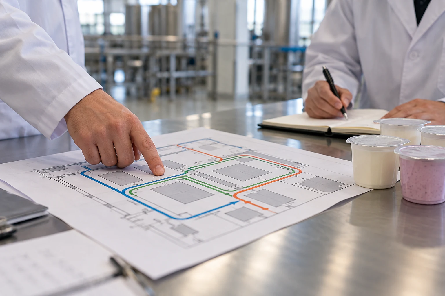
An owner can shorten the distance to a cleaning station and still fail to clean two production areas within the available window. Another can buy multiple stations while leaving their shared hot-water or return requirement unresolved. The useful centralized vs decentralized CIP comparison therefore needs two drawings: a physical circuit map and a resource schedule. They answer different questions, and both influence the capital scope.
1. List Cleaning Objects and Release Windows Before Locating the Room
Start with the tanks, pipe routes, processing packages and filling interfaces that require a defined cleaning arrangement. Identify the actual cleaning method and the requirements established by the relevant technical team for each object. The list should distinguish objects that can share a circuit from those requiring different arrangements or scheduling.
Add when each object must become available for production. One area may stop earlier, another may need to continue operating, and a later campaign may depend on a particular circuit being released first. A total daily cleaning duration does not reveal those dependencies.
Tetra Pak’s Coconut Handbook describes a complete CIP system as the station, distribution lines and objects to be cleaned, and discusses central and distributed arrangements. For an owner, that means the process starts at the object and its duty—not at a convenient unused room.
Create a circuit register with the cleaning object, product/soil basis, supply and return route, required window and allowed concurrent activity. Keep unknown requirements visible rather than assigning one standard recipe to every object. This register can then inform the station position, the number of usable resources and the connected utility and controls scope.
For example, give a remote blending vessel its own row rather than bury it under “mixing area.” Show whether its transfer line belongs to the same object, who supplies its return connection and whether packaging can run while that duty occurs. A missing answer becomes an assigned design question before station procurement.
2. Compare Central and Satellite Arrangements at Their Real Boundaries
A central arrangement gathers selected preparation or media-handling functions in a common location and distributes cleaning fluids to production circuits. A satellite arrangement distributes selected station functions nearer the objects. The distinction affects routing and interfaces; it does not by itself establish a lower installed cost or a better cleaning outcome.
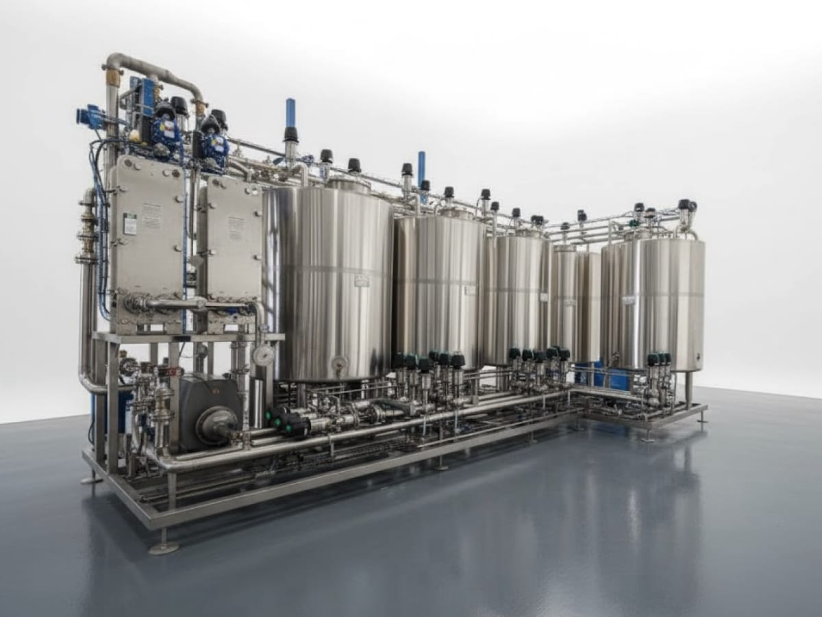
DPS’s CIP offering describes custom design and fabrication connected with vessels, process circuits, piping, controls and third-party equipment. The architecture comparison should therefore show which functions reside in the station package, which remain in the distribution network and what the receiving equipment requires.
Ask each concept to state the independent pressure lines or other relevant resources actually included. A central room can contain more than one independently usable line, while two satellites may still depend on a shared utility that prevents concurrent duty. Comparing “one room” with “two rooms” misses that engineering distinction.
Include media handling, recovery where appropriate, return destinations and the means of establishing the required conditions at the object. A shorter local pipe route may reduce one inventory while adding other station equipment. The decision needs a complete architecture and operating basis rather than a preference for centralized or distributed labels.
Make the quotation boundary visible on a marked-up circuit: station outlet, remote connection, return inlet and control handshake. If a satellite quote includes a local return vessel but the central quote excludes equivalent handling, reconcile that difference before comparing totals. Otherwise the spreadsheet compares different systems under the same cleaning label.
| Interface | Central Concept | Satellite Concept |
|---|---|---|
| Distribution | Longer routes may connect remote objects | Selected functions placed nearer objects |
| Media handling | Shared station functions can be consolidated | Define what remains shared versus local |
| Concurrency | Depends on included resources and utilities | Also depends on resources and shared utilities |
| Returns | Collect and control the defined returning circuits | Assign local return/recovery and shared interfaces |
| Expansion | Extend routes or add defined resources | Add/modify satellites and common support as required |
3. Calculate Route Inventory without Calling It Water Savings
Consider two hypothetical routes with the same 50 mm internal diameter. The central concept has 200 m of combined supply and return pipe; a satellite concept has 80 m. Using internal volume equals π × diameter squared ÷ four × length, their line inventories are approximately 392.7 and 157.1 liters respectively.
The calculated difference is about 235.6 liters of pipe inventory. It excludes the cleaning objects, station vessels, branches and actual operating sequence. The pipe lengths and diameter are arbitrary inputs, not recommended design dimensions or measurements from a DPS project.
That difference is not automatically a saving of 235.6 liters of water per cycle. Media recovery, displacement, rinse strategy, circuit splitting and the actual cleaning requirements determine consumption. The useful result is a routing quantity the team can connect to pump duty, handling and the selected sequence—not a marketed resource saving derived from geometry alone.
Have each concept state its actual route lengths and internal sizes rather than use room-to-room straight-line distance. Vertical sections, detours, branches and the final connection to the object matter. If the layout changes later, refresh the route basis because an apparently local station can acquire a different distribution commitment through detailed design.
As a drawing review, trace one route from the proposed station along its intended corridor, up to the service level and back from the object. Record the length source beside each segment. Replacing that route with an eighty-meter concept later changes the illustration only if both alternatives still serve the same defined object.
4. Separate the Room-Location Decision from Cleaning Concurrency
Assume two hypothetical circuit duties occupy their assigned resource for ninety and sixty minutes. The figures are placeholders for already established duties, not cleaning recommendations. One shared resource doing them sequentially needs 150 minutes before any additional transition or release work.
Two independently usable resources could finish those two duties in ninety minutes if simultaneous operation is supported and other dependencies permit it. That could be two satellites or two suitable lines within a central concept. A central architecture should not be penalized by assuming it can only serve one duty at a time.
Against an invented 120-minute production window, the sequential case is thirty minutes short while the two-resource case has thirty minutes before additional work. The owner still needs to account for the actual transitions, checks and release conditions, and confirm common utilities support concurrency.
Use this distinction when reviewing bids. A lower total may provide only one resource while the production plan assumes two. Conversely, adding a second station may create no usable overlap if both require the same constrained support. The schedule should identify the resource, its duty and the shared conditions enabling the proposed parallel operation.
A useful bid question is: which two duties can actually overlap at the stated utility condition? Ask the supplier to identify the supporting line or resource, not just the number of connections. If a second connection waits for the first, represent that waiting time on the operating schedule rather than counting it as concurrent capacity.
| Concept Resource Arrangement | Duty Sequence | Calculated Occupied Time |
|---|---|---|
| One shared resource | 90 + 60 minutes sequentially | 150 minutes |
| Two supported independent resources | 90 and 60 minutes concurrently | 90 minutes maximum |
| Central room with two supported lines | Same concurrent assumption | 90 minutes maximum |
| Available example window | Before extra checks/transitions | 120 minutes |
5. Trace Supply, Return and Service Access Through the Building
The circuit map should connect the station to the real cleaning object and its return destination. Mark route interfaces, isolation locations and the final connection arrangements required by the design. A line ending at the production-room wall does not complete the equipment interface.
Review the position with the process and building teams. A remote route can cross future rooms or consume access needed for another function. A satellite can reduce distribution distance while requiring local service space, utility connections and media-handling work. These are scope differences to show, not reasons to assume one architecture is inherently compact.
DPS process engineering includes coordinated layout and simultaneous utility analysis. For CIP, those deliverables should connect the physical route with the operating resource model. The distribution drawing and schedule must describe the same circuits and concurrency.
Require actual supplier information for the station package and receiving equipment where it affects layout. Identify which connection or access allowance remains provisional. That prevents a station from being located using one arrangement while the object supplier later assumes another return path or controls boundary.
In a room review, show where an operator reaches the station and where a removed component goes during service. Identify the nearby production route that would be affected by temporary work. The architecture can then include a practical maintenance-access arrangement without assuming the food corridor doubles as unrestricted service space.
6. Plan CIP Tie-Ins Around Real Production Windows
In its Albertsons CIP and compressed-air upgrade account, DPS describes prefabrication and staged connections, with three planned interruptions each under four hours and no reported unplanned interruption. Those planned windows were part of the project.
The relevant architecture lesson is the interface between new infrastructure and retained production. A new central station, local satellite or distribution change can require connections to existing objects, utilities and controls. The owner needs a sequence that identifies which functions are unavailable during each stage and what must be checked before the retained system returns to its defined duty.
Develop a connection register from the circuit drawings. Assign the physical endpoint, responsible package, preparation work, required production condition and verification for the stage. Use it to distinguish work that can be completed beforehand from work that genuinely belongs in the constrained connection window.
The case does not make every CIP addition a three-window project. Its practical value is the prepared sequence: prefabrication, connection details and production planning were treated together. Apply that discipline to the actual central or satellite concept so the apparent equipment saving is not offset by an unplanned field interface or an operating commitment the site cannot accommodate.
For a retained circuit, the connection sheet should show the last acceptable production state before isolation and the intended verified state after reconnection. Assign the person releasing that stage. This converts a vague overnight installation allowance into a defined handover between production, installation and the team responsible for returning the circuit to use.
7. Specify the Return and Sequence Information Needed by the Architecture
A station controller and a plant cleaning sequence need an agreed boundary. Identify how the selected circuit is recognized, what confirms the relevant valves or equipment are in the required state and what conditions permit a duty to begin or end. These functions should follow the designed process rather than a generic automation package name.
Treat supply and return information according to the actual circuit. An outward flow indication does not by itself establish the condition returning from a remote object. The design team must identify which measurements and actions are needed and where they belong; this article does not prescribe an instrument list or cleaning acceptance threshold.
DPS automation and controls describes process review, narratives, sequencing and integration. The useful capital output is a functional boundary linking the station, distribution and receiving equipment, with ownership of normal actions, exceptions and restart.
Test one relevant failure or unavailable state during design review: for example, the requested object is not ready or the required return condition has not been established. Document the permitted response and responsibility. That exposes controls scope an architecture quotation may otherwise leave to the owner without identifying it.
Consider a packaging interface that reports “available” while a connected vessel is still assigned to production. The narrative must resolve which state governs the requested cleaning action and how conflicting requests are handled. Settling that ownership before programming is more useful than adding an unassigned communications cable to the equipment list.
8. Choose a Circuit Strategy That the Plant Can Build and Operate
Compare each viable concept using actual routes, supported concurrency, connected utilities and a defined controls boundary. Price the station packages and the distribution work together. Shorter pipe inventory or another local station is one part of that decision, not the final investment answer.
Reserve specific future connections where justified by a credible production scenario. Show the later circuit, the space and utility implications and what connection work would interrupt existing duty. An unassigned future branch can become a new interface project rather than the simple expansion the owner expected.
For a DPS engagement, bring the cleaning-object register, required release windows, current circuit drawings and available utility information. Ask for the central/satellite comparison, resource schedule, route quantities and staged connection scope that address the actual plant. Keep the cleaning procedure and its required verification with the relevant technical and food safety owners.
The chosen architecture should make three things understandable: how each object is served, when the resources can serve it and how the system can be connected or expanded. When those answers agree, the capital proposal describes useful cleaning infrastructure rather than a room location with the critical operating interfaces left outside it.
Record the chosen tradeoff in the approval: for example, retain centralized preparation but add a supported second line because the two release windows overlap. Alternatively, move a defined function locally because the installed route creates an unacceptable building conflict. That explanation gives later purchasers a reason to preserve the architecture’s essential features.
FAQ
Does a central CIP room mean one circuit at a time?
No. Concurrency depends on the resources and utilities included. A central concept can have multiple suitable lines; several satellites can still share a constrained supporting resource.
Do shorter routes guarantee lower water use?
No. The geometry example calculates pipe inventory only. Actual consumption depends on the circuit, media handling, recovery and established cleaning sequence.
What should be mapped before locating a station?
Identify the cleaning objects, required release windows, actual supply/return routes, shared utilities and control interfaces. Use these to assess station locations and resource needs.
How should cleaning windows be compared across quotations?
Compare the independent resources actually included, shared utility constraints and the circuit duties that can overlap. Add the relevant transition, checking and release time before judging whether each concept fits the production window.
Can satellite stations be connected without interrupting production?
The actual interfaces and sequence determine that. DPS’s published case had planned interruptions; it does not support a zero-total-downtime promise for another project.
What controls work belongs in the comparison?
Define circuit selection, readiness, required actions and evidence, exceptions and restart ownership across station and plant equipment. A controller purchase alone does not assign the complete sequence.
Sources and Calculation Notes
Checked October 27, 2026. DPS case statements are attributed company reports, not independently audited performance. The numerical illustration is hypothetical; concept photographs are not project documentation.
- DPS — CIP Systems — Custom connected-system scope.
- DPS — CIP and Air Upgrade — Attributed prepared/staged connection example.
- DPS — Process Engineering and Design — Layout, utility and equipment coordination.
- DPS — Automation and Controls — Narratives and system sequencing.
- Tetra Pak — Cleaning of Processing Equipment — Station/distribution/object boundary and central/distributed concepts.