DPS Process Equipment
Cleaning Systems Built Around the Process
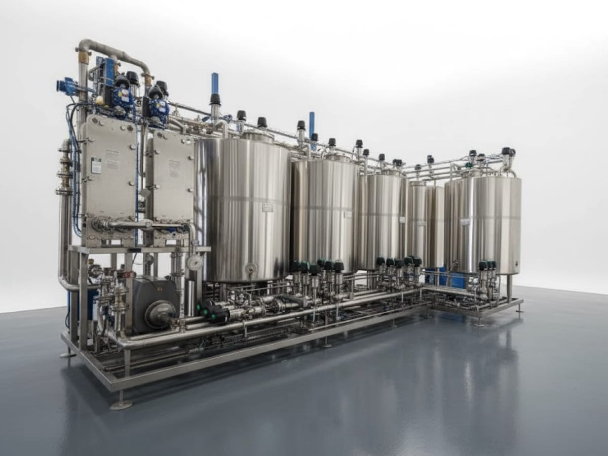
CIP Systems
Design · Build · Manage
Coordinate tank volumes, cleaning circuits, spray devices, pumps, chemical dosing, and automation in one defined CIP scope. DPS develops the package around the equipment, soils, utilities, and changeovers at your facility.
CIP Systems
Define the Cleaning Duty Before the Skid
A clean-in-place system circulates wash, rinse, and sanitizing solutions through vessels, heat exchangers, filling equipment, and process piping. Its design starts with the soil load, product changeovers, vessel geometry, pipe routes, and available cleaning window. Supply and return capacity, flow velocity, temperature, chemical concentration, and drainability become a coordinated cleaning basis.
DPS connects the skid specification with process engineering, utility loads, instrumentation, and control sequences. New systems and retrofit scopes can include recovery tanks, automated dosing, circuit expansion, and PLC or SCADA integration. Agree the cleaning acceptance criteria, test methods, owner responsibilities, and required records before fabrication and commissioning. Include manual cleaning outside automated circuits and identify who will approve sanitation acceptance and validation requirements. Record production interfaces, access and future circuit needs in the agreed equipment and integration scope.
Selected Equipment Program
Choose the Configuration.
Define the Duty.
Start with these program options, then confirm working capacity, the production sequence, and the package boundaries against your application.
- Capacity
- 100, 200, 500, 1,000, or 5,000 gal platform options
- Number of Vessels
- 2, 3, or 4
- Number of Circuits
- 1, 2, or 3+
- Valve Options
- Sanitary butterfly or custom mix-proof valves
- Standards
- 316 stainless steel; NSF sanitary requirements defined for the selected package
- Controls
- Fully automatic, controls-ready configuration
Design Parameters
Specify What the Process Needs.
Platform capacities of 100–5,000 gal and 1, 2, or 3+ circuits describe package options. The detailed ranges below describe individual supply tanks and independent circuits across a facility. These are different design boundaries; confirm vessel roles, useful volume, simultaneous demand, materials, applicable standards, and acceptance requirements in the project proposal.
| Parameter | Configuration & Engineering Basis |
|---|---|
| System Configurations | Single-tank, multi-tank, or eductor-based recovery CIP; portable or centralized skid-mounted arrangements |
| Supply Tank Capacity | 50–1,500 gal per wash, rinse, sanitize, or recovery tank, selected for the circuit duty |
| Circuit Capacity | 2–20+ independent CIP circuits per facility; define simultaneous operation and skid allocation |
| Materials of Construction | 304 or 316L stainless steel; specify food-contact suitability for all wetted surfaces and cleaning chemicals |
| Sanitary Standards | Define applicable 3-A Sanitary Standards, Tri-Clamp connections, and sloped drain construction; confirm certification requirements separately |
| Supply Pump Sizing | Sanitary centrifugal pumps with a 10–300 GPM design reference, sized against each circuit's calculated system head |
| Spray Device Integration | Rotary spray heads, static spray balls, or high-impact tank cleaning devices; establish coverage verification against vessel geometry and design flow |
| Chemical Dosing | Conductivity-based automatic concentration control; assess compatibility with caustic, acid, PAA, and chlorinated sanitizers |
| Heating Method | Steam injection, electric immersion, or shell-and-tube heat exchange; wash-temperature references up to 185°F, subject to the cleaning duty and materials |
| Controls & Automation | PLC sequencing, HMI touchscreen, SCADA interfaces, recipe-based cycles, and data logging within the agreed controls scope |
| Regulatory Requirements | Assess FDA 21 CFR Part 117, USDA-FSIS, SQF, BRC, FSSC 22000, and PMO/Grade A dairy requirements for the specific application; define evidence and responsible parties |
| Documentation | Define the functional design specification, I/O list, weld records, material certificates, FAT protocol, and CIP verification or validation support package |
Applications & Industries
Different Products.
A Defined Process Basis.
Match the equipment to the product, cleaning requirements, and operating sequence. Explore the wider industry context before fixing the specification.
Dairy Processing
Coordinate milk, cultured-product, and ingredient circuits with cleaning temperatures, product-contact materials, recovery strategy, and the dairy plant's verification requirements.
Beverage Production
Plan cleaning routes for mixing tanks, fermentation or holding vessels, transfer piping, and filling equipment around the available changeover windows.
Sauces, Marinades & Dressings
Define cleaning conditions for viscous residues, oil phases, particulates, and allergen changeovers across blending vessels, heat exchangers, and transfer lines.
Co-Packing & Contract Manufacturing
Connect multiple product recipes with circuit selection, chemical controls, cleaning records, and owner-approved release criteria between campaigns.
Before Selecting This Equipment
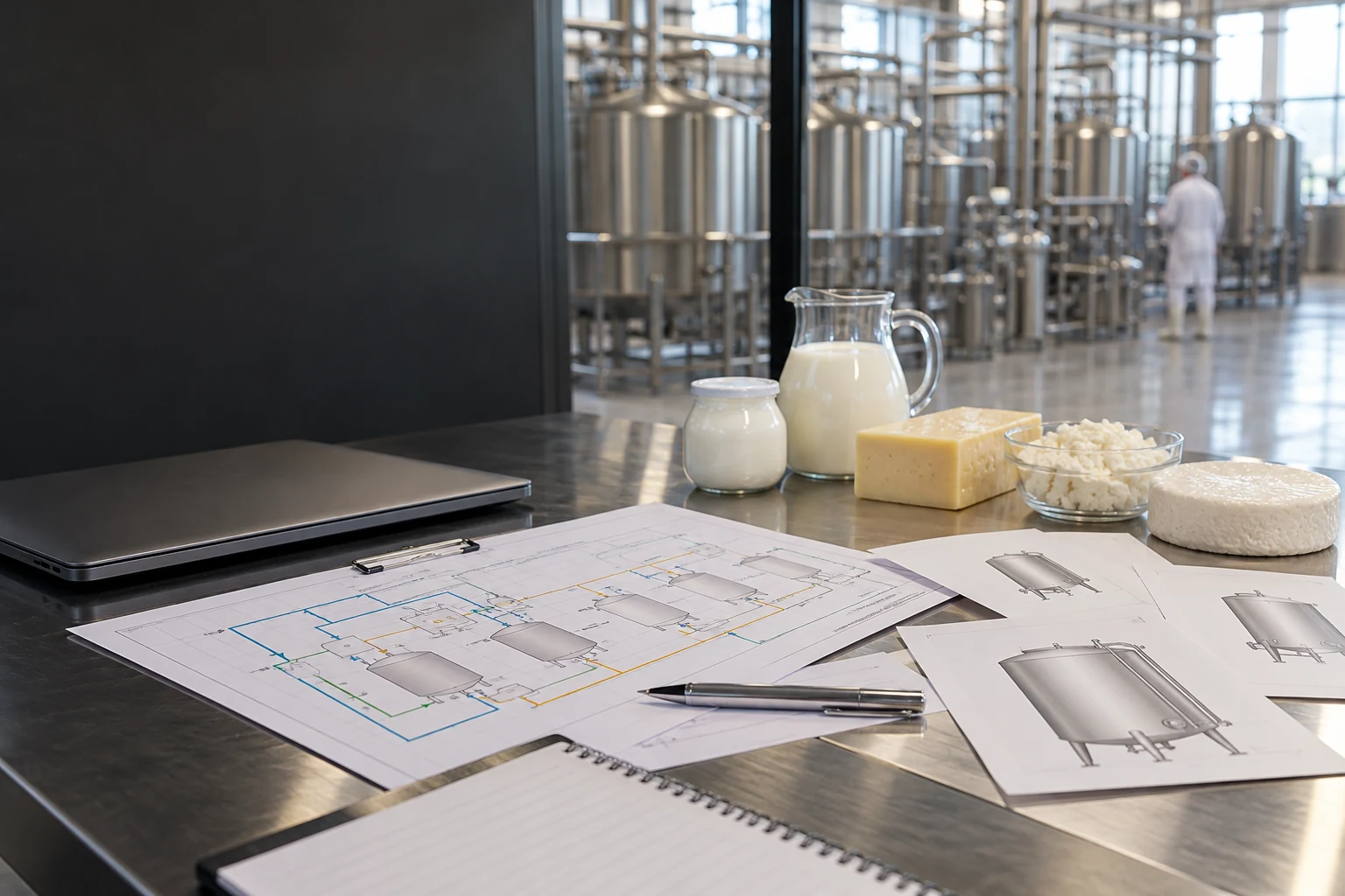
Food Plant CIP Infrastructure: What to Specify Before Selecting Process Equipment
Specify cleaning objects, supply and return duties, product hold-up, controls and connection work before selecting food process equipment and CIP infrastructure.

Food Plant CIP Layout: Centralized vs Satellite Cleaning Infrastructure
Compare central and satellite CIP through circuit routing, pipe inventory, cleaning concurrency, returns and staged connections in a live food plant.
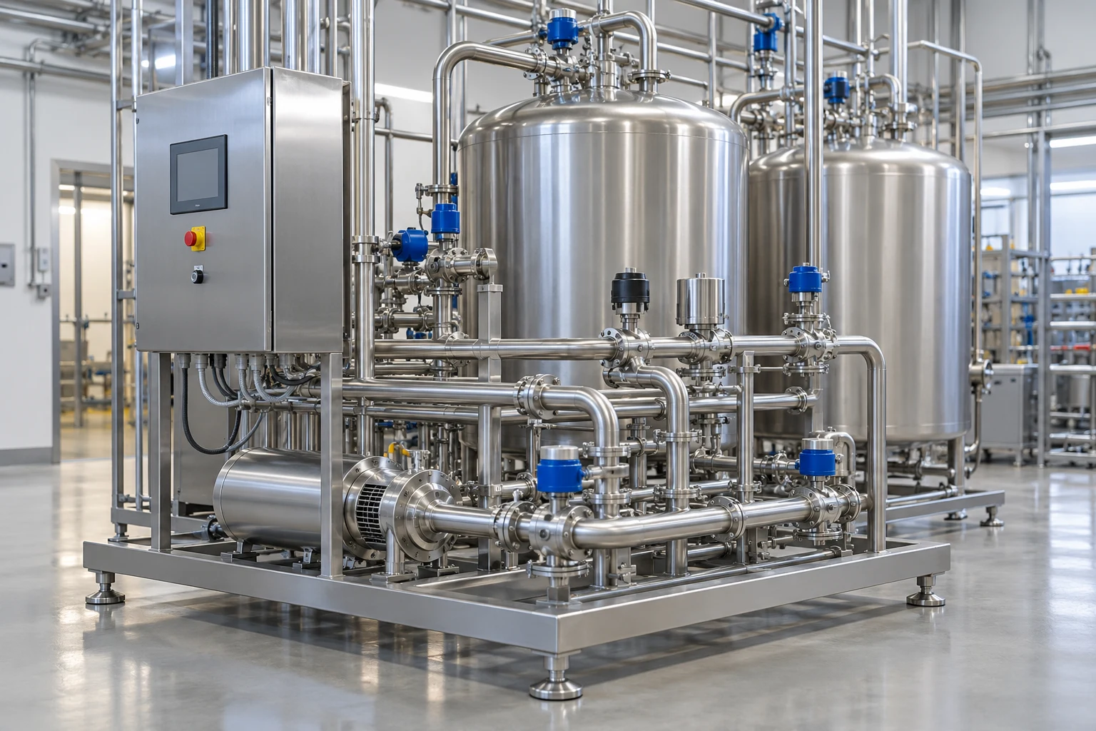
Multi-SKU CIP Systems
Connect the cleaning circuit, recipe sequence, supply and return conditions, quality release and resource cost to a reviewable CIP investment.
- Which vessels and lines need cleaning, and which circuits must operate at the same time?
- What soils, cleaning chemicals, temperatures, verification methods, and changeover windows define the duty?
- What supply, return, utility, controls, and documentation interfaces are already in place?
How Is the CIP System Schedule Confirmed?
Detailed CIP scopes carry indicative 10–18 week references, while platform packages use an 18–20 week planning allowance. Confirm which scope and starting milestone apply in the current proposal. A two-tank, four-circuit skid differs from a centralized system serving 15 or more circuits with SCADA, recipes, and custom HMI work. Engineering approval, circuit count, fabrication workload, testing, transport, site readiness, and the master project schedule determine the agreed delivery programme.
Can an Existing CIP System Be Upgraded?
An assessment can examine the existing tanks, pumps, routing, controls, and cleaning results before defining an upgrade. Potential work includes replacing manual chemical additions with automatic dosing, conductivity-based phase detection, PLC or SCADA integration, and additional circuits for new production lines. Verify retained equipment condition and compatibility, identify performance gaps, and agree the testing needed for the modified system.
How Is Cleaning Coverage Verified Inside a Vessel?
Review spray-device selection and location against vessel diameter, sidewall height, head profile, nozzle penetrations, and design flow. Commissioning can include riboflavin testing or another agreed visual coverage method. The food-safety programme determines the cycle records, coverage results, ATP testing, or microbiological evidence required, including any USDA or PMO obligations. Coverage testing supports the agreed verification or validation programme; acceptance criteria and approval responsibilities remain explicit.
Can the System Serve DPS and Third-Party Equipment?
Yes. Coordinate spray bosses, supply and return ports, valve locations, and cleaning requirements during design. For installed third-party equipment, confirm dimensions, connection sizes, port elevations, and required flow through a site survey and supplier information. Circuit-specific recipes can define flow, temperature, chemical concentration, and duration for each asset, with the controls interfaces and shared-supply limitations established in the functional specification.
What Maintenance and Ongoing Support Should Be Planned?
Plan gasket, spray-device, check-valve, pump-seal, and wear inspections against equipment manufacturer instructions. Verify conductivity probes, temperature sensors, and flow meters at intervals defined by the food-safety and maintenance plans. Include the O&M manual, recommended spare parts, and preventive-maintenance intervals in the agreed handover package. Continuing facility support can be separately scoped, with access, responsibilities, availability, and commercial terms confirmed.
Explore the Rest of the Line.
View All Equipment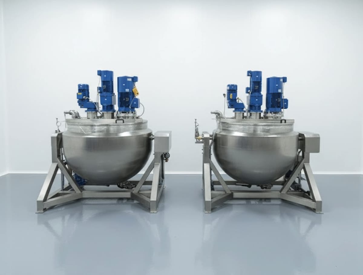
Kettles & Cookers
200–1,000 gal
Match the vessel to the recipe and production cycle. Coordinate working volume, jacket duty, agitation, discharge, utilities, cleaning, and batch records before selecting a kettle.
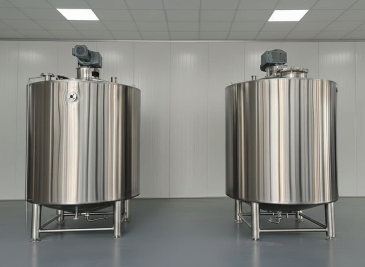
Tanks & Vessels
500–25,000 gal
Define the vessel's role in the process before selecting volume or fittings. Coordinate product duty, tank form, agitation, jackets, nozzles, cleaning, instrumentation, and fabrication records.
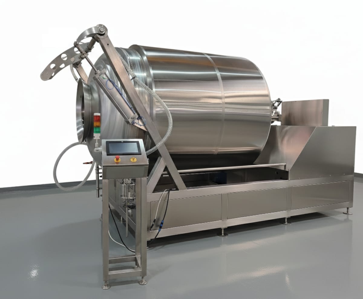
Tumblers & Marinators
500–5,000 lb
Define the product and effective batch load before selecting a tumbler. Coordinate drum action, vacuum, temperature, handling, cleaning, recipes, and the upstream and downstream line.
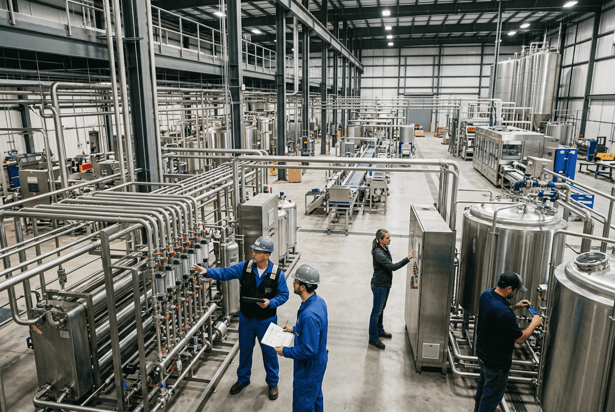
The Next Conversation
Start With the Circuits and Cleaning Conditions
Share the equipment list, P&IDs, soil and chemical requirements, cleaning windows, utility data, and controls platform. DPS can help define the skid, facility interfaces, test plan, and supply responsibilities.
Discuss Your Project